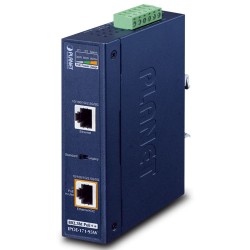
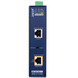
- Διαθεσιμοτητα: Διαθέσιμο
- Κατασκευαστης: PLANET
- Κωδικος Προϊοντος: IPOE-171-95W
- Βαρος: 0.62kg
- Διαστασεις: 8.78 x 13.50 x 3.20
Advanced Industrial Multi-Gigabit and 802.3bt PoE++ Network Solution
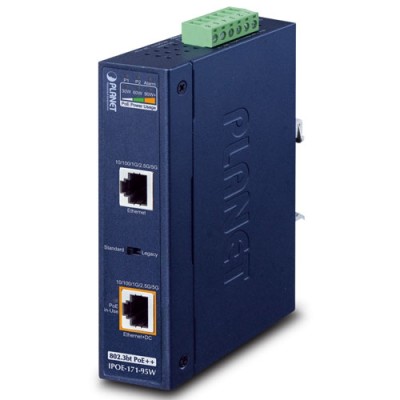
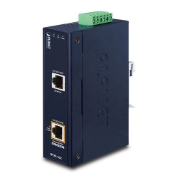
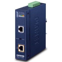
PLANET IPOE-171-95W is a Single-Port, Industrial 802.3bt Power over Ethernet Injector with a maximum of up to 95 watts of power output over Ethernet cables. It is also equipped with two 100M/1G/2.5G/5GBASE-T RJ45 copper interfaces to handle extremely large amounts of data transmission.

It is designed specifically to meet the demand for growing higher power required network equipment such as:
- Lighting
- All-in-one touch PC
- Remote digital signage display
- Other network devices that need higher power to work normall
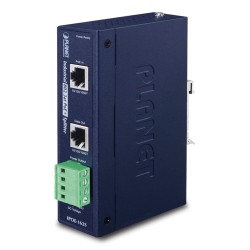
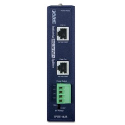
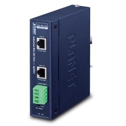
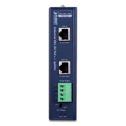
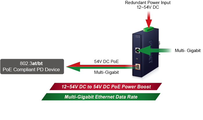
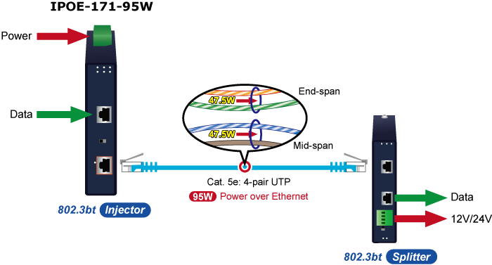
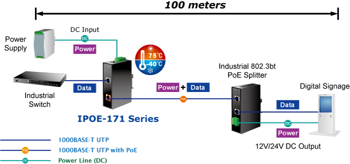
The IPOE-171-95W delivers the Ethernet digital data with 54V DC power over the twisted-pair cables as a 95-watt Power over Ethernet Injector, and the connected ultra Power over Ethernet splitter, the IPOE-173S, will separate the digital data and the power into three optional outputs (12V/24V DC) with distance up to 100 meters.
Convenient and Reliable Power System
To facilitate the 802.3bt PoE++ usage with commonly used 12~54V DC power input for transportation and industrial-level applications, the IPOE-171-95W adopts 12~54V DC to 54V power boost technology to solve power source issue but does not require special power supplies. The IPOE-171-95W provides an integrated power solution with a wide range of voltages (12~54V DC) for worldwide operability. It also provides dual-redundant, reversible polarity 12~54V DC power supply inputs for high availability applications.
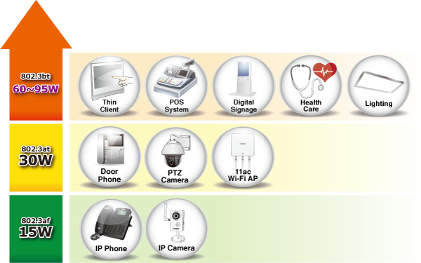
95 watts of Power over 4-pair UTP
Instead of delivering power over 2-pair twisted UTP – be it end-span (Pins 1, 2, 3 and 6) or mid-span (Pins 4, 5, 7 and 8), the IPOE-171-95W provides the capability to source up to 95 watts of power by using all the four pairs of standard Cat. 5e/6 Ethernet cabling.
PoE Standard | IEEE 802.3af (802.3at Type 1) | IEEE 802.3at (802.3at Type 2) | IEEE 802.3bt (802.3bt Type 3) | IEEE 802.3bt (802.3bt Type 4) |
Maximum Power delivered by PSE | 15.4 watts | 30 watts | 60 watts | 95 watts |
Power Available at PD | 12.95 watts | 25.5 watts | 51 watts | 71 watts |
Voltage Range | 48V | 50~57V | 52~57V | 52~57V |
Twisted-pair Used | 2-pair | 4-pair | 4-pair | |
Supported Modes | End-span or Mid-span | End-span + Mid-span | End-span + Mid-span | |
Supported Cabling | Cat. 3/5/5e/6/6A | Cat. 5e/6/6A | Cat. 5e/6/6A | |
Intelligent LED Indicator for Power Input and Real-time PoE Usage
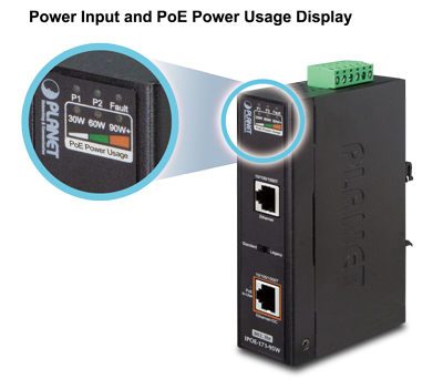
The IPOE-171-95W helps users to monitor the current status of power input and PoE power usage easily and efficiently via its advanced LED indication. “Power Input” allows user to know the status of power input. “PoE Power Usage” displayed on the panel of the IPOE-171-95W has three LED indicators of different power usages. Via the power usage LED, the IPOE-171-95W enables the administrator to monitor the status of the power usage of the connected PDs in real time.
High Compatibility and Compact Size Design
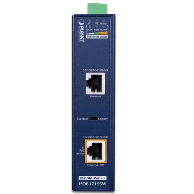
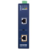
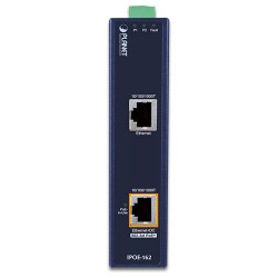
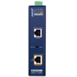
It is easy to install the PoE injector by way of Plug and Play and comes with simple troubleshooting, making it easy for business and home users to own it. Besides, the IPOE-171-95W comes in compact housing, and provides two DC redundant power inputs, two power LEDs, fault LED and PoE-in-Use LED. Two RJ45 ports -- Ethernet port and Ethernet + DC port – are on the front panel.
Moreover, the IPOE-171-95W, when switched to the Legacy mode and Force mode, provides power to those PD devices which do not fully follow the IEEE 802.3at/bt standard. It is helpful to enhance the compatibility of IPOE-171-95W with other PDs.
Simply plug in the Ethernet cables and DC power wire, and the IPOE-171-95W is ready to provide high-speed network communication and the 802.3bt PoE injector functions simultaneously with no need of software configuration.
Quick and Easy Cabling Installation for PoE Network Deployment
Backward compatible with both 802.3at PoE standards, the IPOE-171-95W allows users to flexibly deploy standard and high powered devices to transfer data and power simultaneously through one Ethernet cable for up to 100 meters. The IPOE-171-95W frees the security IP camera and wireless AP deployment from restrictions of power outlet locations and the additional AC wiring. It thus reduces cables and eliminates the need for electrical outlets on the wall, ceiling or any unreachable place, and most of all, it reduces installation time.
Stable Operating Performance under Difficult Environments
Today, the PoE demand expands from commercial applications to many critical networks in the harsh environment. The IPOE-171 series will be one of the ideal solutions that provide a high level of immunity against electromagnetic interference and heavy electrical surges typical of environments found on plant floors or in curb side traffic control cabinets. The IPOE-171 series can operate stably under temperature range from -40 to 75 degrees C which enables the users to conveniently apply the device in almost any location of the network. The IPOE-171 series is also equipped with a compact IP30 standard metal case that allows either DIN-rail or wall mounting for efficient use of cabinet space.
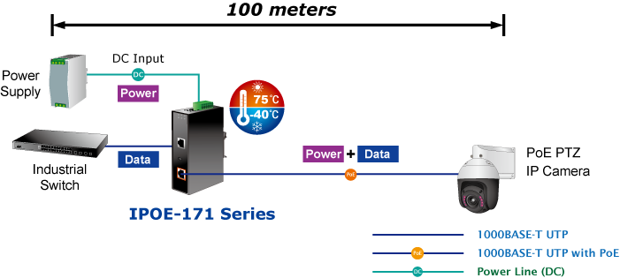
Installation of 802.3bt PoE Injector
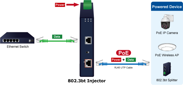
Due to the backward capability of IEEE 802.3at PoE standard, the IPOE-171-95W can directly connect with any IEEE 802.3at end-nodes, such as PTZ (pan, tilt & zoom) speed dome IP cameras, color touch-screen Voice over IP (VoIP) telephones, and multi-channel wireless LAN access points.
Installation of 802.3bt PoE Injector and Splitter
For a place which is hard to find the power inlet, the IPOE-171-95W and IPOE-173S operate as a pair to provide the easiest way to power your Ethernet devices which need high power input, such as PTZ network cameras, PTZ speed dome cameras, color touch-screen Voice over IP (VoIP) telephones, and multi-channel wireless LAN access points installed on the top of the building or used in enterprise office or home.
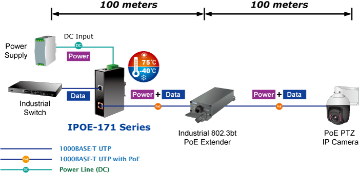
Extended Installation of IEEE 802.3bt Injector and PoE Network
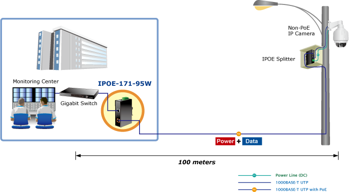
Is 100-meter cable long enough for a wide range of IP surveillance deployments? The answer is certainly not. To achieve the benefits of IP surveillance and also the long-distance IP camera distribution, the IPOE-171-95W and PLANET PoE Extender, IPOE-E302, can be a quick and cost-effective option. In the simplest application, the PoE Extender enables a PoE IP camera to be installed up to 200 meters away from the IPOE-171-95W. The IPOE-171-95W delivers PoE power over the first 100 meters to the PoE Extender over UTP cables, and then the PoE Extender forwards the Ethernet data and remaining PoE power to the remote PoE IP cameras.
Interface
- 2 Multi-Gigabit RJ45 interfaces
- 1-port Data + Power output
- 1-port Data input
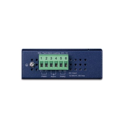
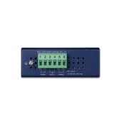
- 1 terminal block for master and slave power input. (Power Range: 12 ~ 54V DC redundant power)
- 1 PoE mode (standard/legacy and force) DIP switch
Power over Ethernet
- Complies with IEEE 802.3at/bt PoE end-span/mid-span PSE
- Supports PoE power up to 95 watts for PoE port
- Auto-detection of PoE IEEE 802.3at/bt equipment and devices from being damaged by incorrect installation
- Monitors the status of the total PoE usage in real time
- Remote power feeding up to 100m
Hardware
- IP30 slim type metal case
- LED indicators for Power LED , PoE-in-Use LED and PoE Usage LED
Industrial Case and Installation
- Solid wall mount or DIN-rail mount installation
- Supports 6KV DC Ethernet ESD protection
- -40 to 75 degrees C operating temperature
| Hardware Specifications | |
|---|---|
| Interface | Input Port:1 x RJ45 STP Data In Output Port:1 x RJ45 STP PoE (Data + Power) Out Input power terminal block:1 |
| Network Cable | Twisted-pair cable up to 100 meters (328ft) 10BASE-T: 4-pair UTP Cat. 3, 4, 5, 5e, 6, 6A 100BASE-TX: 4-pair UTP Cat. 5, 5e, 6, 6A 1G/2.5G: 4-pair UTP Cat. 5e, 6, 6A 5G: 4-pair UTP Cat. 6, 6A |
| LED Indicators | System: Power 1 (Green), Power 2 (Green), Fault (Red) PoE Port: PoE-in-Use x 1 (Amber) PoE Usage: PoE Usage x 3 (Amber) |
| Data Rate | 10M/100M/1G/2.5G/5Gbps |
| ESD Protection | 6KV DC |
| Enclosure | Metal case |
| Dimensions (W x D x H) | 135 x 87.8 x 32 mm |
| Weight | 443g |
| Power Requirements | DC 12~54V, 6A max. |
| Unit Output Voltage | DC 54V |
| Power Consumption | 120 watts max. |
| No. of devices that can be powered | 1 |
| Installation | DIN-rail kit or wall-mount ear |
| Alarm | Provides one relay output for power failure Alarm Relay current carry ability: 1A @ DC 24V |
| Enclosure | IP30 slim type metal case |
| Power over Ethernet | |
| PoE Standard | IEEE 802.3at/bt PSE |
| PoE Power Output Budget | DC 54V / 95-watt PoE via 4-pair DC 54V / 36-watt PoE via 2-pair |
| PoE Power Output | DC 24V~54V input: Max. 89.5W@1m cable Max. 75W@100m cable DC 12V input: Max. 60W@1m cable Max. 52W@100m cable |
| PoE Power Supply Type | End-span + Mid-span |
| Power Pin Assignment | Pair 1 End-span: 1/2 (-), 3/6 (+) Pair 2 Mid-span: 4/5 (+), 7/8 (-) |
| PoE Mode | Standard mode Legacy and Force mode |
| Standards Conformance | |
| Standards Compliance | IEEE 802.3 10BASE-T Ethernet IEEE 802.3u 100BASE-TX Fast Ethernet IEEE 802.3ab 1000BASE-T Gigabit Ethernet IEEE 802.3bz 2.5G/5GBASE-T IEEE 802.3bt 4-pair Power over Ethernet Plus Plus IEEE 802.3at Power over Ethernet Plus |
| Regulatory Compliance | FCC Part 15 Class A, CE |
| Environment | |
| Operating Temperature | -40 ~ 75 degrees C |
| Storage Temperature | -40 ~ 85 degrees C |
| Operating Humidity | 5 ~ 90%, relative humidity, non-condensing |
| Storage Humidity | 5 ~ 90%, relative humidity, non-condensing |
| Standard Accessories | |
| Package Contents | IPOE-171-95W User's manual Wall-mount kit Dust cap |

